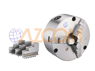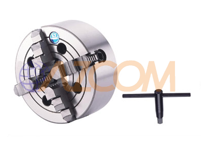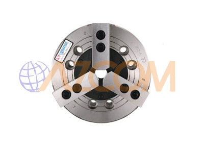
Hydraulic Chucks Vertex N-A
Describe:
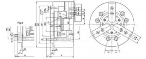
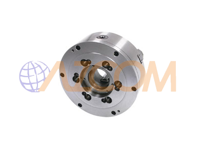
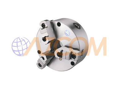
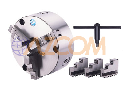
Hydraulic chuck for clamping the part and transmitting rotation to the part on a CNC lathe.
– The hydraulic chuck is more advantageous than the chuck, usually fast, no effortless and can automatically clamp. Used on CNC lathes.
– The wedge-shaped transmission structure for the hydraulic chuck clamping force is very solid.
– The VERTEX hydraulic chuck has 20% wider openings.
– The rotation speed and clamping force of the hydraulic chuck are also about 20% greater than the normal chuck.
– N-200A hydraulic chuck fitted with ASA B5.9 type spindle connector.
– The chuck is made of alloy steel. The chuck’s surface is hardened and polished. For high precision and long-term working ability.
– With hydraulic cylinder type: M1036; M1246; M1552; M1875; M2091; M2511.
– Alternate chuck: soft pin for VHC water chuck and hard pin for HJ water chuck.
Technical parameters:
| ORDER NO.
DIM |
N-205A4 | N-206A5 | N-208A5 | N-208A6 | N-210A6 | N-210A8 | N-212A8 | N-215A8 | N-215A11 |
| Through-Hole (mm) | 033 | 045 | 052 | 052 | 075 | 075 | 091 | 0117.5 | 0117.5 |
| Plunger stroke (mm) | 10 | 12 | 16 | 16 | 19 | 19 | 23 | 23 | 23 |
| Jaw Stroke (mm) | 5.4 | 5.5 | 7.4 | 7.4 | 8.8 | 8.8 | 10.6 | 10.6 | 10.6 |
| Max. Draw Bar Pull Force (kgf | 1700 | 2200 | 3400 | 3400 | 4300 | 4300 | 5500 | 7240 | 7240 |
| Max. Gripping Force (kgf) | 3600 | 5700 | 8800 | 8800 | 11000 | 11000 | 14300 | 18355 | 18355 |
| Max. Operating Pressure (kgt/ cm2) | 29.6 | 28.5 | 26.5 | 26.5 | 27.5 | 27.5 | 27.5 | 23.5 | 23.5 |
| Max. Speed (r.p.m.) | 7000 | 6000 | 4900 | 4900 | 4200 | 4200 | 3300 | 2500 | 2500 |
| Weight (kgs) | 6.9 | 142 | 25.8 | 24.05 | 40.9 | 37.4 | 63.2 | 134 | 127 |
| Matching Cylinder | M1036 | M1246 | M1552 | M1552 | M1875 | M1875 | M2091 | M2511 | M2511 |
| Matching Soft Jaw | VHC05 | VHC06 | VHC08 | VHC08 | VHC10 | VHC10 | VHC12 | VHC15 | VHC15 |
| Matching Hard Jaw | HJ05 | HJ06 | HJ08 | HJ08 | HJ10 | HJ10 | HJ12 | HJ15 | HJ15 |
| CODE NO. | 5002-080 | 5002-081 | 5002-082 | 5002-083 | 5002-084 | 5002-085 | 5002-086 | 5002-087 | 5002-088 |
| A | 135 | 169 | 210 | 201 | 254 | 254 | 304 | 381 | 381 |
| B | 71 | 91 | 109 | 103 | 120 | 113 | 122 | 160 | 149 |
| G | 96 | 116 | 133.35 | 150 | 171.45 | 190 | 190 | 235 | 260 |
| D | 14 | 20 | 25 | 25 | 30 | 30 | 30 | 43 | 43 |
| E | 15 | 15 | 23 | 17 | 25 | 18 | 18 | 33 | 22 |
| F | 65.513 | 82.563 | 82.563 | 106.375 | 106.375 | 139.719 | 139.719 | 139.719 | 196.869 |
| C | 110 | 140 | 170 | 170 | 22C | 220 | 220 | 300 | 300 |
| H | 82.55 | 104.78 | 104 78 | 133.35 | 133.35 | 171.45 | 171.45 | 171.45 | 235 |
| J | 15.5 | 16 | 13 | 18 | 18 | 24 | 25 | 24 | 28 |
| K | 3xM10 | 6xM10 | 6xM12 | 6xM12 | 6xM16 | 6xM16 | 6xM16 | 6xM20 | 6xM20 |
| L | 33 | 45 | 52 | 52 | 75 | 75 | 91 | 117.5 | 117 5 |
| M | 4 | 5 | 5 | 5 | 5 | 5 | 6 | 6 | 6 |
| N max. | 26 5 | 32 | 38.7 | 38.7 | 51 | 51 | 61.3 | 82 | 82 |
| N min. | 23.8 | 29.25 | 35 | 35 | 46.6 | 46.6 | 56 | 76.7 | 76.7 |
| 0 max. | 19.75 | 22.75 | 29.75 | 29.75 | 33.75 | 33.75 | 45.75 | 46.75 | 46.75 |
| 0 min. | 7.75 | 9.25 | 14.75 | 14.75 | 14.25 | 14.25 | 15.75 | 13.75 | 13.75 |
| p max. | 16 | 26 | 37.5 | 31.5 | 33.5 | 26.5 | 26 | 40 | 29 |
| p min. | 6 | 14 | 21.5 | 15.5 | 14.5 | 7.5 | 3 | 17 | 6 |
| Q | 2 | 2 | 2 | 2 | 2 | 2 | 2 | 5 | 5 |
| R | 10 | 12 | 14 | 14 | 16 | 16 | 21 | 24 | 24 |
| s | 20 | 19 | 20 5 | 20.5 | 25 | 25 | 28 | 43 | 43 |
| T | 23 | 32 | 37 | 37 | 42 | 42 | 52 | 62 | 62 |
| u max. | M40X1.5 | M55X2.0 | M60X2.0 | M60X2.0 | M85X2.0 | M85X2.0 | M100x2.0 | M130x2.0 | M 130×2.0 |
| V | 3xM6 | 3xM6 | 6xM10 | 3xM6 | 6xM12 | 6xM8 | 6xM8 | 6xM16 | 3xM10 |
| w | 45 | 60 | 66 | 66 | 94 | 94 | 108 | 139 | 139 |
| REFER FIG. | Fig-1 | Fiq-1 | Fiq-2 | Fig-1 | Fiq-2 | Fiq-1 | Fig-1 | Fiq-2 | Fig-1 |